
In most buildings the fire alarm system, the CCTV system, access control, voice alarm and building management are each installed separately. Each works on its own. The problem is that when there is a fire, they have to behave as one.
Integration is not connecting these systems together. It is writing down in advance which event triggers which response, and then testing it.
What has to happen on alarm
When the alarm sounds, several things need to happen in the building at once:
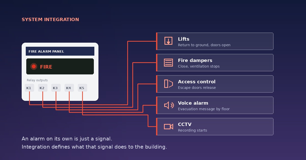
- Lifts return to ground floor, open their doors and stay there, so nobody attempts to evacuate by lift.
- Fire dampers close and ventilation stops, so smoke is not carried through ductwork into other compartments.
- Smoke extract fans start, keeping escape routes clear.
- Access control doors release. Nobody without a card is trapped.
- The voice alarm system operates, delivering evacuation messages to the relevant floors.
- Cameras begin recording, so footage exists for the post-incident review.
None of this happens by itself. Each is the result of a command leaving the fire panel.
The cause and effect matrix
The document that defines integration is the cause and effect matrix. It has two axes: triggering events down the rows, triggered outputs across the columns.
For example: "Third floor corridor detector in alarm → third floor sounders + second and fourth floor sounders + lift homing + third floor damper closed + third floor doors released"
This matrix is written at design stage and approved by the client. A scenario improvised on site during commissioning is a scenario that has not been tested.
Where the matrix is never written, the typical outcome is this: the system is installed, the alarm sounds, and nothing happens. The devices are all there, but nobody defined what any of them should do.
How the interface is made
A fire panel talks to other systems in three ways:
Volt-free contacts (relay outputs). The most common and most reliable method. The panel operates a relay and the receiving system reads it on its own input. There is no software dependency and no protocol mismatch. Lift homing, damper closure and door release are usually built this way.
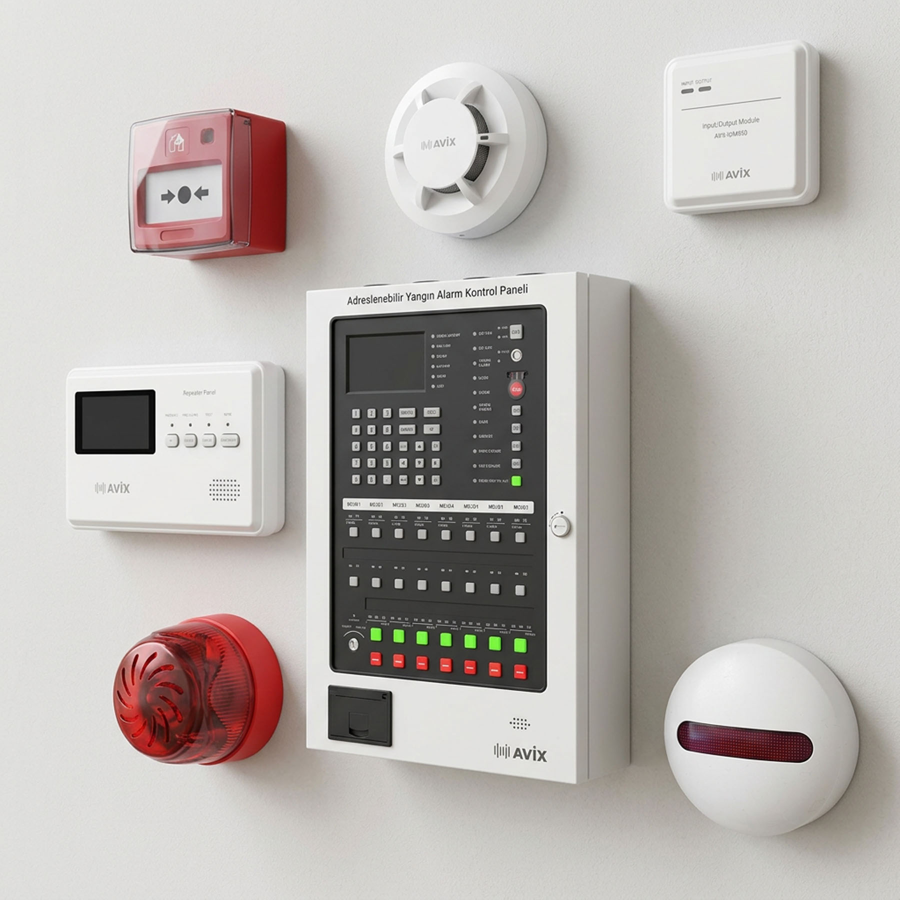
Input/output modules. In an addressable system these sit on the loop. The panel manages each module at its own address, so commands can be issued per floor or per compartment. They fall under EN 54-18.
Data protocol. Modbus, BACnet or proprietary protocols are used for building management and head-end software. This route carries far richer information, but life safety functions are not left to it — a protocol link is for monitoring and reporting, not for commands.
One rule: fire commands, it does not receive
This is the most frequently violated principle in integration. The fire alarm system issues commands to other systems; other systems do not control the fire system.
An arrangement where building management can silence, shut down or disable the fire panel is not acceptable. Equally, a software fault elsewhere must not be able to stop the fire system working.
In practice this means the fire side has its own supply, its own wiring and its own monitoring.
Access control and door release
This deserves its own heading, because it has both a legal and a technical dimension.
Electrically controlled locks on escape routes must release on fire alarm. The standard way to achieve this is a fail-safe lock that opens when power is removed: the fire panel drops a relay, the lock loses supply, the door opens.
The reverse arrangement, where an active signal from the fire system unlocks the door, is dangerous: if the cable is cut, the door stays locked.
Security and life safety conflict here, and life safety takes precedence. An arrangement that keeps an escape door locked out of concern about theft is defensible neither to an inspector nor in court.
Commissioning tests
Integration is not complete when the cables are connected. It is complete when every scenario has been tested individually.
Each row of the matrix is proved separately: the triggering device is actually operated, every expected output is verified by observation, and the result is recorded. Someone watches the lift actually descend, the damper actually close, the door actually open.
"The relay operates" is not sufficient. What must be verified is that the receiving system sees that relay and behaves correctly.
Three problems we see most often on site
No documentation. The system is installed but no matrix was ever written. Three years later, when something needs changing, nobody knows what is connected to what.
Divided responsibility. One company installed the fire system, another the lifts, a third the building management. The lift does not home on alarm and each company points at the other. Integration needs a single owner.
Never tested. Cables connected, not one scenario proved end to end. The first real alarm becomes the first test.
How we work
The order we follow on integration projects:
Survey of what exists. Which systems are in the building, which manufacturer, what interface each supports. Most older systems offer nothing beyond volt-free contacts; it is better to know that at the start.
Writing the matrix. With the client, floor by floor and compartment by compartment. No work starts on site before it is approved.
Interface design. Deciding which connection is made by volt-free contact, which by module, and which by protocol.
Installation and commissioning. Every scenario tested individually and recorded.
Handover. Cause and effect matrix, interface drawings, device address list and test records are delivered with the project.
To review the integration of your existing system or discuss a new project, you can request a free site survey.