

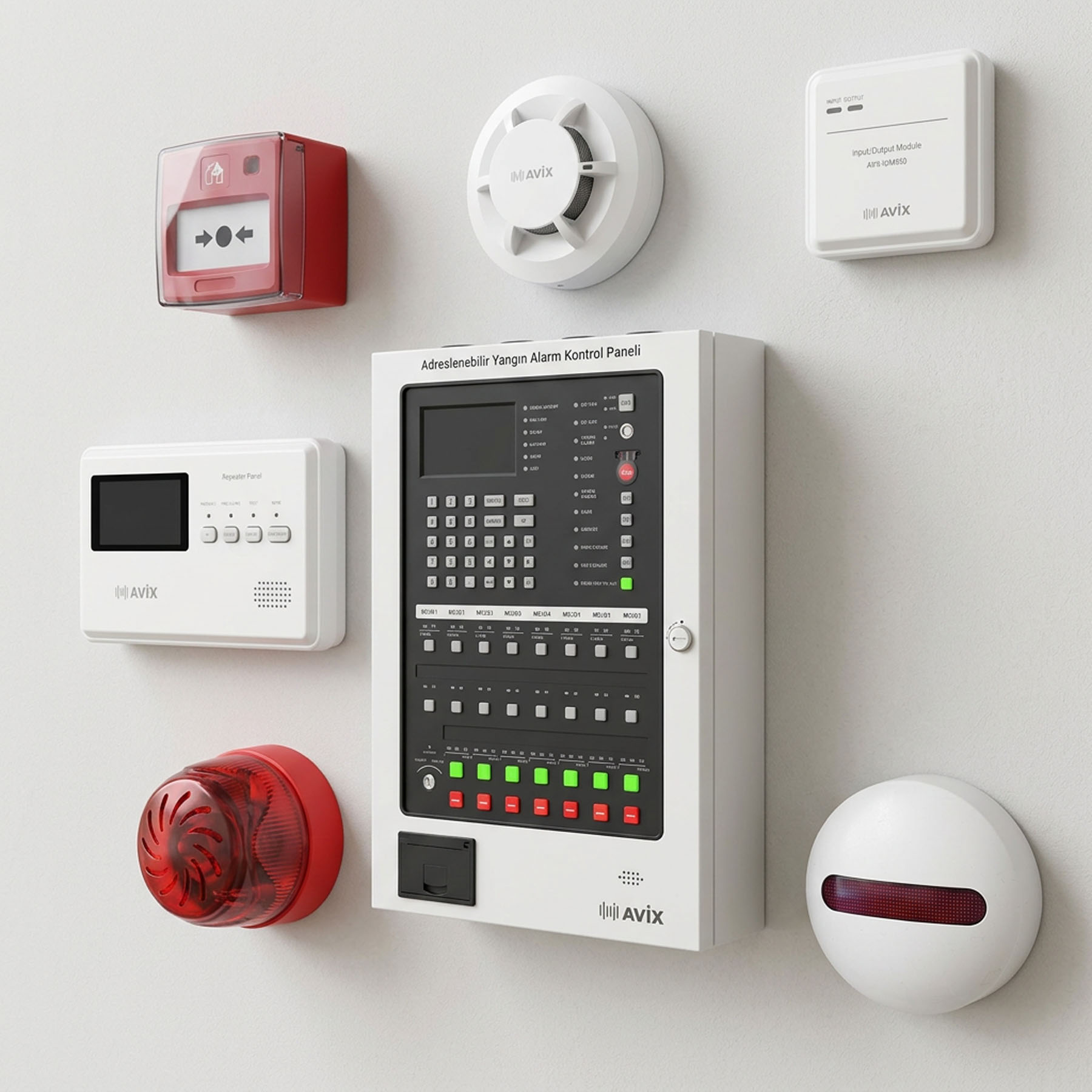
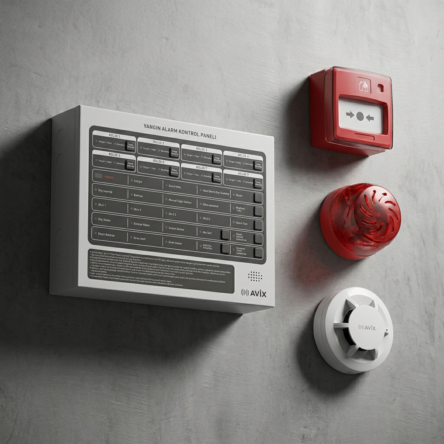
Addressable systems are the form of fire detection used in large, heavily compartmented buildings. The difference from a conventional system can be stated in one sentence, but that sentence changes everything: the panel knows which device went into alarm.
This article covers what you need to know before moving to an addressable system. The conventional side is covered in a separate article.
Loop logic: what an address means
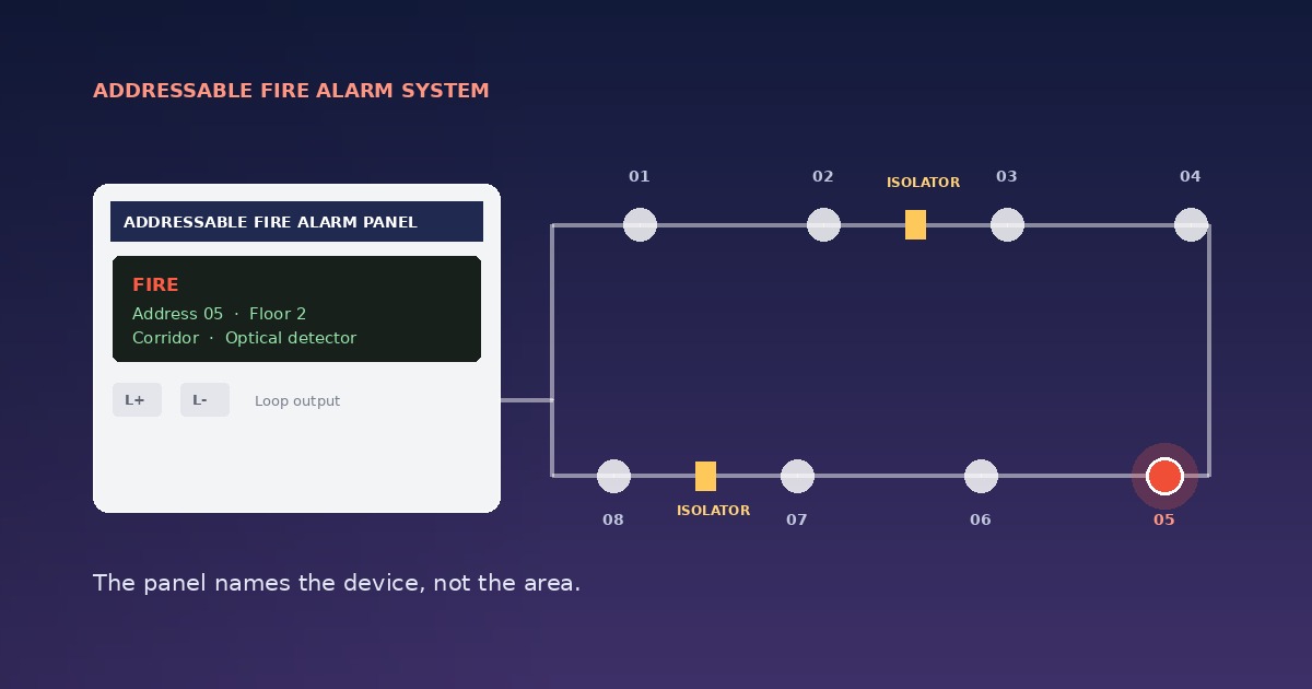
The basic unit of an addressable panel is the loop. A loop is a circuit that leaves the panel, passes through the devices and returns to the panel. Every device on it — detector, call point, sounder, module — has its own address.
On alarm, the panel reports: "Second floor, corridor, optical detector 47."
A conventional panel would only give you the zone, and whoever responded would go and search. With addressing there is no search. The screen names the device.
The real difference between loop and zone
Summarising the two systems as "more expensive, better" misses the point. The difference is structural:
- Resolution. A zone points at an area; an address points at a device.
- Wiring. A conventional system needs a separate circuit per zone. An addressable loop covers a whole floor on one circuit. As device count rises, addressable wiring costs drop below conventional.
- Feedback. An addressable device continuously reports its contamination level, its faults and whether it is responding at all. A conventional detector is silent.
- Cause and effect. Device level addressing is what allows rules such as "if the detector on floor three goes into alarm, send the lift to ground".
How many devices on one loop
Address capacity varies by manufacturer; common panels address between 100 and 250 devices per loop. In practice that figure is not used as a working limit, because two other constraints bite first:
Current budget. The standby and alarm currents of every device on the loop are added up. Sounders and output modules consume this budget quickly. The current capacity can run out well before the address capacity does.
Cable resistance. As loop length increases, the voltage seen by the last device on the circuit drops. Cable cross-section and total length are calculated at design stage.
A practical rule: do not fill the address capacity. Loading a loop to 70–80 per cent leaves room for devices added later.
Isolators: the most frequently skipped part
A loop is a circuit, and a short circuit at a single point could in principle disable the whole of it. An isolator module prevents this: it separates the faulty section from the circuit and the rest carries on working.
Isolators fall under EN 54-17 and they are not optional. Standard design practice is that a single fault should not disable more than a defined number of devices, which is why isolators are placed at fire compartment boundaries and floor transitions.
This is the most common omission on site: the loop is run, the devices are fitted, the isolators are left out. The system works on the day it is commissioned; a year later a cable gets crushed and an entire floor goes blind.
Some detectors carry an isolator in the base or body. That reduces the number of separate modules needed, but it does not remove the need for the design calculation.
Loop or spur
Loop wiring can be run two ways:
Loop. The cable leaves the panel, passes the devices and returns. If the circuit breaks at any point, devices continue to be fed from both ends. This is the proper installation form for an addressable system.
Spur (radial). The cable leaves the panel and ends. If it breaks, everything beyond the break goes dead. Used for short branches; not chosen for the main run.
Cause and effect programming
This is the least used and most valuable part of an addressable system. The panel can be programmed so that a signal from a given device triggers a given output:
- Lifts returning to ground floor and opening their doors
- Fire dampers closing and smoke extract fans starting
- Access control doors releasing
- Phased evacuation messages by floor
- The relevant camera starting to record
These connections are made through input/output modules, which fall under EN 54-18. The cause and effect matrix is written at design stage, not improvised during commissioning.
For more on getting systems to talk to each other, see our system integration page.
Pre-alarm and contamination reporting
An addressable detector continuously reports the value it measures. This has two practical consequences:
Pre-alarm. When the value approaches the alarm threshold, the panel warns without raising a general alarm. Someone goes and looks. This stage is what usually separates a false alarm from a real fire.
Contamination reporting. When a detector gets dirty, the panel flags it as a fault. In a conventional system a dirty detector first starts producing false alarms, and then that zone gets disabled. With addressing, cleaning is scheduled before it becomes a problem.
When addressable becomes necessary
A conventional system is not enough when:
- Compartment count is high. Hotels, halls of residence, hospitals, office floors. Zone based detection slows the response.
- There are many storeys. Since each floor needs its own zone, conventional panel capacity fills quickly and wiring becomes unwieldy.
- Cause and effect is required. Lifts, dampers, evacuation messaging, access control.
- False alarms are expensive. A production line stopping, surgery interrupted, a hotel evacuated.
- The system will grow. On phased projects, adding a device to a loop is easier than pulling a new zone circuit.
Against that, a small workshop, a single storey warehouse or a building with few compartments does not justify the cost. To work through which system suits your building, see our system selection guide.
What to require from a panel
EN 54-2 and EN 54-4 compliance. Separate certifications for the control panel and the power supply.
Standby duration. 24 hours standby plus 30 minutes in alarm, on battery. As device count on the loop rises, so does the battery capacity needed; the calculation done for a conventional system will not carry over.
Loop fault monitoring. The panel should separately indicate an open circuit, a short circuit and a device that has stopped responding.
Event log. The panel should hold a history of alarms, faults and operations. It is the first place anyone looks during an inspection or a fault investigation.
Three common mistakes
Skipping the isolators. The most common and most expensive error. The system works the day it is installed and goes blind across a whole floor at the first cable fault.
Filling the loop. A system with 245 devices on a 250 address capacity will need a new panel at the first refurbishment.
Not handing over the address list. The panel says "detector 47", but if no document shows where 47 is, the entire advantage of addressing is lost. The device address list and system drawings should be delivered with the project.
Summary
An addressable system is the right answer for buildings with high compartment and storey counts. Its advantage comes not from the panel being expensive but from the system knowing what happened and where. That advantage only materialises when the isolator scheme is designed properly and the address list is handed over.
For support with loop planning and panel selection, you can request a free site survey.
